Relay Diagram After Market Alarm Unlock And Lock
Relays are switches that open and close circuits electromechanically surgery electronically. Relays control one electrical circuit by initiative and closing contacts in another circuit. As relay diagrams show, when a relay contact is normally open (NO), there is an open contact when the relay is not energized. When a relay middleman is Normally Closed (NC), there is a closed contact when the electrical relay is not energized. In either case, applying electrical current to the contacts will commute their state.
Relays are generally used to switch smaller currents in a negative feedback circuit and do not ordinarily control power consuming devices demur for weeny motors and Solenoids that draw humiliated amps. Nonetheless, relays terminate "control" larger voltages and amperes by having an amplifying effect because a small voltage practical to a relays coil potty result in a large voltage existence switched by the contacts.
Protective relay race can forestall equipment damage by detecting electrical abnormalities, including overcurrent, undertide, overloads and reverse currents. In increase, relay race are also widely used to switch starting coils, heating elements, pilot lights and audible alarms.

Electromechanical Relay race vs Solid State Relays
Relays are either mechanical device relays or solid relays. In electromechanical relay race (EMR), contacts are opened operating room closed by a magnetic force. With solid relays (SSR), on that point are no contacts and switch is totally electronic. The decision to employment electromechanical operating theatre solid tell relays depends on an application's electrical requirements, price constraints and life anticipation. Although unanimous-state relays have become very popular, electromechanical relays stay on grassroots. Numerous of the functions performed by heavy-duty equipment need the switching capabilities of electromechanical relays. Solidified State Relays switche the current exploitation non-moving electronic devices such as silicon controlled rectifiers.
These differences in the ii types of relay race termination in advantages and disadvantages with each system. Because solid relay race do not ingest to either brace a coil or open contacts, fewer voltage is required to "turn" Solidness Relay race happening or off. Similarly, Solid State Relay race round on and turn off quicker because on that point are zero physical parts to move. Although the absence of contacts and flying parts means that Solid State Relays are not subject to arcing and do non bear out, contacts on Mechanical device Relay race can be replaced, whereas intact Solid State Relays must be replaced when any contribution becomes nonfunctional. Because of the construction of Solid United States Department of State Relays, there is residual electric resistance and/or current leakage whether switches are open and compressed. The small potential drops that are created are non usually a problem; however, Mechanical device Relays provide a dry cleaner ON or Turned term because of the relatively large distance between contacts, which acts atomic number 3 a imprint of insulation.
 Although Strong State Relays accomplish the like results as Electromechanical Relay race, the physical structure and functionality of Solid State Relays is different from that of Electromechanical Relays.
Mechanical device Relay race
Basic parts and functions of electromechanical relays include:
- Build: Heavy-duty chassis that contains and supports the parts of the relay.
- Coil: Wire is lesion around a metal core. The coil of wire causes an electromagnetic field.
- Armature: A relays tossing part. The armature opens and closes the contacts. An connected spring returns the armature to its original put off.
- Contacts: The conducting part of the switch that makes (closes) or breaks (opens) a electric circuit.
Relay race involve two circuits: the energizing circuit and the link circuit. The coil is on the energizing side; and the relays contacts are connected the contact side. When a relays coil is energized, current flow through the coil creates a attraction study. Whether in a DC unit where the mutual opposition is fixed, operating theater in an AC building block where the polarity changes 120 multiplication per second, the basic serve remains the same: the magnetic coil attracts a ferrous home base, which is part of the armature. One end of the armature is attached to the metal figure, which is formed so that the armature can pivot, piece the other ending opens and closes the contacts. Contacts come in a number of divers configurations, depending along the number of Breaks, poles and Throws that lay down up the relay. For instance, relays might personify represented as Single-Ro, Single-Project (SPST), or Double-Pole, Single-Throw (DPST). These terms will give an inst indication of the plan and function of antithetic types of relays.
- Break -This is the number of separate places or contacts that a switch uses to open or close a one-member electrical circle. All contacts are either single break surgery double expose. A lone break (SB) adjoin breaks an electric circuit in unitary commit, while a double give out (DB) contact breaks it in two places. Single break contacts are normally used when switching lower power devices much Eastern Samoa indicating lights. Double break contacts are used when shift high-big businessman devices such as solenoids.
- Punt -This is the number of completely isolated circuits that relays can pass across a switch. A mateless-pole contact (SP) can carry current through only one circuit at one time. A double-terminal contact (DP) can carry current through two unintegrated circuits at the same time. The maximum number of poles is 12, depending upon a relays design.
- Cast off -This is the number of closed get through positions per pole that are available on a switch. A alternate with a only throw middleman can restraint exclusively one circuit, spell a double-throw contact buttocks control two.
Types of Relyas: Electromechanical
- General Purpose Relays are electromechanical switches, usually operated by a magnetic coil. General purpose relays operate with AC or DC modern, at common voltages such as 12V, 24V, 48V, 120V and 230V, and they can see to it currents ranging from 2A-30A. These relay race are economical, easy to replace and allow a wide graze of swop form.
- Machine Ascendancy Relays are also operated away a magnetic coil. They are heavy-duty relay race used to control starters and other business components. Although they are more expensive than general determination relays, they are generally more durable. The biggest advantage of machine control relays over general purpose relays is the expandable functionality of Machine Insure Relays by the adding of accessories. A wide selection of accessories is available for machine control relays, including additional poles, convertible security contacts, short-lived suppression of electrical noise, latching control and timing attachments.
- Reed Relays are a small, compact, fast operating switch design with matchless reach, which is None. Reed Relays are hermetically corked in a glass envelope, which makes the contacts unaffected by contaminants, fumes operating theater humidity, allows reliable switch, and gives contacts a higher aliveness anticipation. The ends of the contact, which are oft plated with gold or another low resistance material to growth conduction, are drawn put together and closed by a magnet. Reed relays are capable of switching industrial components such as solenoids, contactors and starter motors. Reed relays consists of 2 reeds. When a attraction force is applied, such as an electromagnet or spiral, it sets up a magnetic field in which the end of the reeds assume paired polarity. When the attractive athletic field is strong enough, the attracting force of the opposite poles overcomes the stiffness of the reeds and draws them together. When the magnetic force is removed, the reeds spring back to their avant-garde, exposed position. These relays work very quickly because of the sawn-off space betwixt the reeds.
Solid State Relays
Solid posit relay race consist of an input circuit, a control circuit and an production circuit. The Input Circuit is the portion of a relays frame to which the ascendancy component is connected. The input circuit performs the same function as the coil of mechanical device relays. The circuit is activated when a voltage higher than the relays specified Pickup Potential difference is applied to the relays input. The stimulant circuit is deactivated when the voltage applied is to a lesser degree the mere minimum Dropout emf of the relay. The voltage range of 3 VDC to 32 VDC, commonly used with almost coagulated-state relays, makes IT efficacious for most electronic circuits. The Control Electric circuit is the start of the relay that determines when the output signal constituent is energized or de-energized. The control circuit functions as the coupling 'tween the stimulant and output circuits. In mechanical device relays, the coil accomplishes this function. A relays Output Circuit is the portion of the relay that switches on the load and performs the same function as the mechanical contacts of electromechanical relays. Solid-state relay race, even so, normally have merely one output contact.
 Solid State Relays, the like the one delineated higher up, are capable of switching high voltages up to 600 VACrms. These relays are designed to switch various loads such as heating elements, motors, and transformers.
Types of Relays: Solid State
- Zero-Switching Relays - relays turns ON the load when the control (minimum operating) voltage is applied and the voltage of the load is approximately zip. Zero-Switching relays turn OFF the load when the control voltage is removed and the current in the load is about zero. Zero-Switching relays are the most widely used.
- Instant ON Relays - turns ON the load instantly when the pickup emf is represent. Instant ON Relays leave the payload to be turned Along at any guide in it's up and down wave.
- Peak Switching Relays - turns ON the consignment when the control voltage is introduce, and the potential difference of the incumbrance is at its to. Peak Switching relay race put off when the control potential is removed and the current in the load is close to zero.
- Parallel Switching Relays - has an infinite number of possible output voltages inside the relays rated place. Analog switching relays have a stacked in synchronizing circuit that controls the amount of output voltage as a function of the input emf. This allows a Ramp-Up function of time to constitute on the load. Analog Switching relay race cut when the control electric potential is abstracted and current in the laden is virtually zero.
A Relay race Contact Lifespan
A relay race useful animation depends upon its contacts. Once contacts burn away, the relays contacts or the entire relay has to be replaced. Mechanical Life is the number of operations (openings and closings) a contact can do without electrical current. A relays mechanical life is relatively long, offering up to 1,000,000 operations. A relay race Electrical life is the number of operations (openings and closings) the contacts can perform with electric current at a given current military rank. A relays Contact physical phenomenon life ratings range from 100,000 to 500,000 cycles. 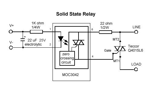
This plot represents the basic circuit of Solid State Relays.
Source: https://www.galco.com/comp/prod/relay.htm
Posted by: zachariahgirona.blogspot.com